
How to modernize machines equipped with encoders with OC or PP HTL outputs?
Machines usually fitted with encoders with OC or PP HTL outputs
Machines with OC outputs
Encoders with the OC output are often found in machines from Asia. The popularity of this interface is caused by its simplicity and very low price. It can be used in simple applications where a high frequency output signal is not required.
Machines with PP HTL outputs
HTL outputs, also known as Push-Pull, hence the PP in the name, are the most popular output interface in incremental encoders. It means most of the machines using this type of encoders, use also the PP HTL output. It is perfectly suited for the machines in which the problem with electromagnetic compatibility occurs. PP HTL outputs are also commonly used in case of high-power drives and inverters that deem the application of an incremental encoder necessary.
How to modernize machines fitted with encoders with OC or PP HTL outputs?
To modernize the machines fitted with encoders or straight edges with OC and PP HTL outputs, the implementation of a line driver is needed.
What is a line driver?
Line driver is an open collector signal converter, that changes digital signal and Push-Pull High-Transistor Logic into a differential signal. The device is mostly used for retrofitting machines equipped with encoders or straight edges with OC and PP HTL output, when a motion controller requires a differential signal. The line driver helps with devices that are not related to measuring systems. It is particularly useful when it is required to send very fast 5V or 24V signals to a considerable distance in an environment with heavy interference.
What is the use of a line driver?
Line driver can be used to:
- change the encoder’s signal that has OC (open collector) output type into the differential signal,
- change the encoder’s signal that has Push-Pull output type into the differential signal.
How does a line driver work?
The primary line driver task is to change digital signals TTL/OC into a differential signal TTL. It means that:
- the TTL digital signal – Transistor-Transistor Logic, which is made of bipolar transistors and defines digital 1 when signal voltage is between 1.5 and 5V, and digital 0 when a signal voltage is between 0V and 0.7V,
as well as
- the OC digital signal – Optical Carrier transmission rates, which are a standardized set of specifications of transmission bandwidth for digital signals that can be carried on Synchronous Optical Networking (SONET) fiber optic networks
are converted into
- the differential signal TTL – signal that employs two complementary voltage signals in order to transmit one information signal (one information signal requires a pair of conductors; one carries the signal and the other carries the inverted signal).
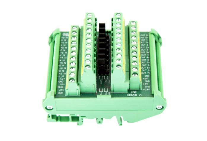
Line Driver by CS-LAB – converter of digital signals TTL/OC into differ. signals TTL
When the machines equipped with encoders with OC or PP HTL outputs should be modernized?
Machines with OC outputs
Machines equipped with the encoders using OC output have many limitations. In case of applications that demand higher repeatability and electromagnetic compatibility, the devices should be modernized and the outputs changed into a more advanced and reliable interface.
Machines with PP HTL outputs
The encoder with a PP HTL output has a tendency to generate voltage drops on its components, which results in heat generation. It means that, in the high state of the output signal, the voltage level will be about 2 to 4 V DC smaller than the supply voltage. In the low state, on the other hand, the user will never be able to reach 0 V, and will always be in the range of approx. 0.5 to 1.5 V. To change that, the modernization of a machine and the change of the output is required.
-
 Pipeline assembly process
Pipeline assembly is definitely one of the most necessary industries of our time. With more and more materials such as water, waste, gas
Pipeline assembly process
Pipeline assembly is definitely one of the most necessary industries of our time. With more and more materials such as water, waste, gas
-
 Repair or replacement of Tesla doors after an accident – which option Is more optimal?
Doors in Tesla vehicles are important both functionally and aesthetically. They play a crucial role in ensuring the safety, comfort, and appearance of
Repair or replacement of Tesla doors after an accident – which option Is more optimal?
Doors in Tesla vehicles are important both functionally and aesthetically. They play a crucial role in ensuring the safety, comfort, and appearance of